

|
Product Details:
|
|
| Place of Origin: | China |
|---|---|
| Brand Name: | Hilink |
| Certification: | CE Rohs |
| Model Number: | 40G QSFP LR4 10KM |
|
Payment & Shipping Terms:
|
|
| Minimum Order Quantity: | 1 pieces |
| Price: | Need to negotiate |
| Packaging Details: | Plastic box+Carton |
| Delivery Time: | 5-8 working day |
| Payment Terms: | T/T, Western Union,Alipay, Paypal/Wechat/Trade Assurance |
| Supply Ability: | 2000 Pieces/Week |
|
Detail Information |
|||
| Use: | Data Center | Data Rate: | 40G |
|---|---|---|---|
| Warranty: | 3 Years | Package: | Plastic Box |
| Delivery Time: | 2-5 Working Days | OEM & ODM: | Acceptable |
| Wavelength: | 1310 | Connector: | LC |
| High Light: | LC Connector Fiber Optic Module,SMF10KM Fiber Optic Module,Fiber Optic Module Transceiver |
||
Product Description
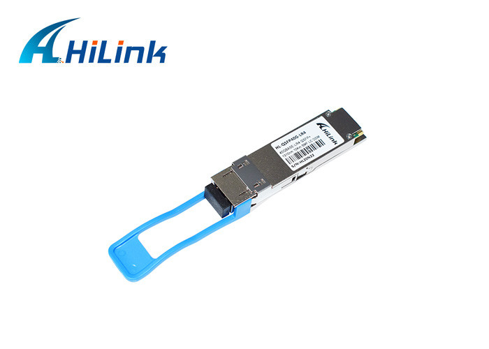
QSFP+, 40GBASE-LR4, SMF, 1270~1330,10KM LC Connector Fiber Optic Module
This product is a transceiver module designed for 2m-10km optical communication
applications. The design is compliant to 40GBASE-LR4 of the IEEE P802.3ba standard. The module converts 4 inputs channels (ch) of 10Gb/s electrical data to 4 CWDM optical signals, and multiplexes them into a single channel for 40Gb/s optical transmission. Reversely, on the receiver side, the module optically de-multiplexes a 40Gb/s input into 4
CWDM channels signals, and converts them to 4 channel output electrical data.
The central wavelengths of the 4 CWDM channels are 1271, 1291, 1311 and 1331 nm as
members of the CWDM wavelength grid defined in ITU-T G.694.2. It contains a duplex LC connector for the optical interface and a 38-pin connector for the electrical interface. To minimize the optical dispersion in the long-haul system, single-mode fiber (SMF) has to be applied in this module.
The product is designed with form factor, optical/electrical connection and digital
diagnostic interface according to the QSFP+ Multi-Source Agreement (MSA). It has been designed to meet the harshest external operating conditions including temperature, humidity and EMI interference.
Optical Characteristics
| Parameter | Symbol | Min | Typical | Max | Unit | Notes | |
| Wavelength Assignment | L0 | 1264.5 | 1271 | 1277.5 | nm | ||
| L1 | 1284.5 | 1291 | 1297.5 | nm | |||
| L2 | 1304.5 | 1311 | 1317.5 | nm | |||
| L3 | 1324.5 | 1331 | 1337.5 | nm | |||
| Transmitter | |||||||
| Side Mode Suppression Ratio | SMSR | 30 | dB | ||||
| Total Average Launch Power | PT | 8.3 | dBm | ||||
| Average Launch Power, each Lane | PAVG | -4 | 2.3 | dBm | |||
| Optical Modulation Amplitude (OMA), each Lane | POMA | -4 | 3.5 | dBm | 1 | ||
| Difference in Launch Power between any Two Lanes (OMA) | Ptx,diff | 6.5 | dB | ||||
| Launch Power in OMA minus Transmitter and Dispersion Penalty (TDP), each Lane | -4.8 | dBm | |||||
| TDP, each Lane | TDP | 2.6 | dB | ||||
| Extinction Ratio | ER | 3.5 | dB | ||||
| Relative Intensity Noise | RIN | -128 | dB/Hz | 12dB reflection | |||
| Optical Return Loss Tolerance | TOL | 20 | dB | ||||
| Transmitter Reflectance | RT | -12 | dB | ||||
| Transmitter Eye Mask Definition {X1, X2, X3, Y1, Y2, Y3} | {0.25, 0.4, 0.45, 0.25, 0.28, 0.4} | ||||||
| Average Launch Power OFF Transmitter, each Lane | Poff | -30 | dBm | ||||
| Receiver | |||||||
| Damage Threshold, each Lane | THd | 3.3 | dBm | 2 | |||
| Total Average Receive Power | 8.3 | dBm | |||||
| Average Receive Power, each Lane | -13.7 | 2.3 | dBm | ||||
| Receiver Reflectance | RR | -26 | dB | ||||
| Receiver Sensitivity (OMA), each Lane | SEN | -11.5 | dBm | ||||
| Stressed Receiver Sensitivity (OMA), each Lane | -9.6 | dBm | 3 | ||||
| Difference in Receive Power between any Two Lanes (OMA) | Prx,diff | 7.5 | dB | ||||
| LOS Assert | LOSA | -28 | dBm | ||||
| LOS Deassert | LOSD | -15 | dBm | ||||
| LOS Hysteresis | LOSH | 0.5 | dB | ||||
| Receiver Electrical 3 dB upper Cutoff Frequency, each Lane | FC | 12.3 | GHz | ||||
| Conditions of Stress Receiver Sensitivity Test (Note 5) | |||||||
| Vertical Eye Closure Penalty, each Lane | 1.9 | dB | |||||
| Stressed Eye J2 Jitter, each Lane | 0.3 | UI | |||||
| Stressed Eye J9 Jitter, each Lane | 0.47 | UI | |||||
Notes:
1. Even if the TDP < 0.8 dB, the OMA min must exceed the minimum value specified here.
2. The receiver shall be able to tolerate, without damage, continuous exposure to a modulated optical input signal having this power level on one lane. The receiver does not have to operate correctly at this input power.
3. Measured with conformance test signal at receiver input for BER = 1x10-12.
4. MVertical eye closure penalty and stressed eye jitter are test conditions for measuring stressed receiver sensitivity. They are not characteristics of the receiver.
Features:
Compliant with 40G Ethernet IEEE802.3ba and 40GBASE-LR4 Standard
QSFP+ MSA compliant
Compliant with QDR/DDR Infiniband data rates
Up to 11.2Gb/s data rate per wavelength
4 CWDM lanes MUX/DEMUX design
Up to 10km transmission on single mode fiber (SMF)
Operating case temperature: 0 to 70℃
Maximum power consumption 2.5W
LC duplex connector
RoHS compliant
Client-side 40G Telecom connections
![]()
![]()
![]()
Package & Shipping
International Express: DHL, FedEx,EMS,TNT, UPS and so on. It takes 3-7 days.
Our Service
OEM/ODM order is available
We promise all the advertised optical modules are brand new and absolutely never use old and refurbished materials. All the optical modules have been through functional test and aging test. We provide 3 years warranty for all the optical transceivers from the date of shipment.
Enter Your Message
| Shenzhen HiLink Technology Co.,Ltd. |
| 11F DongMing Building, Minzhi Street, Longhua District, Shenzhen , China |
| 86-755-2335-7706 |
| steve@hilinktech.com |